The Purchase
I learned to code when I was seven years old on a VTech kids’ computer that happened to have BASIC built in. It had no storage. No hard drive, no save function, nothing. I’d write programs, and when I wanted to show someone, I’d retype the whole thing from paper notes. That experience shaped how I think about everything.
So when I saw Cubetto, a wooden robot that teaches coding to kids as young as three, no screens required, I didn’t just think “cool toy.” I thought this could be the modern equivalent of what that VTech was for me. A way to let my kids discover the mental framing of programming early, the idea that you can break a problem into steps, give instructions, and watch a system execute them. I’m not trying to turn my daughters into engineers. But the ability to think in systems isn’t exactly becoming less relevant, and if the spark is there, I’d love for them to find it the way I did, by playing with something that just happens to teach logic.
This isn’t some random toy. Cubetto was created by Primo Toys, founded by two Italian designers in London. They ran a Kickstarter in 2013 that raised over $1.6 million, making it one of the most funded education projects on the platform. Arduino co-founder Massimo Banzi endorsed it publicly. It won a Cannes Lion and a Red Dot award. The original production run, 800 units built by hand in what they called “The Big Build,” had the energy of a genuine maker project backed by real engineering conviction.
I bought the Cubetto Explore Bundle: robot, five playmats, and accessories. About $450 all-in.
Then my kids tried to use it.
The Problems
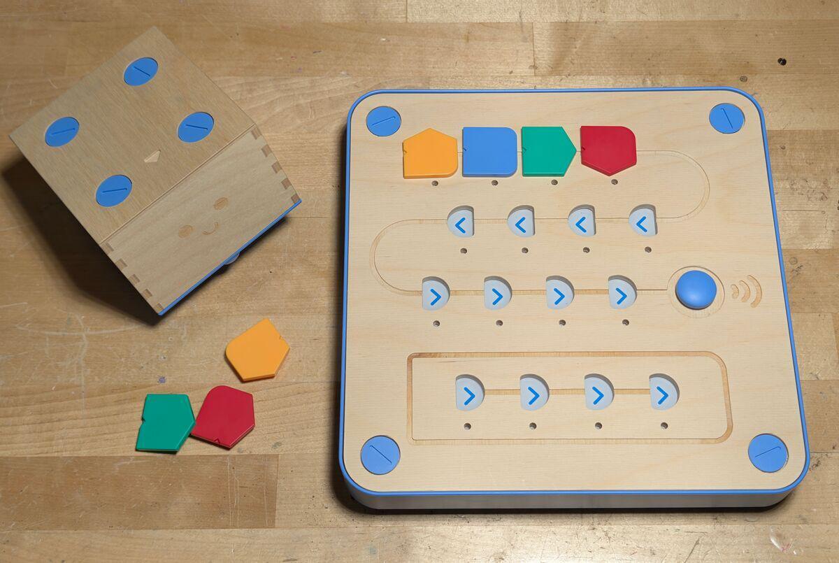
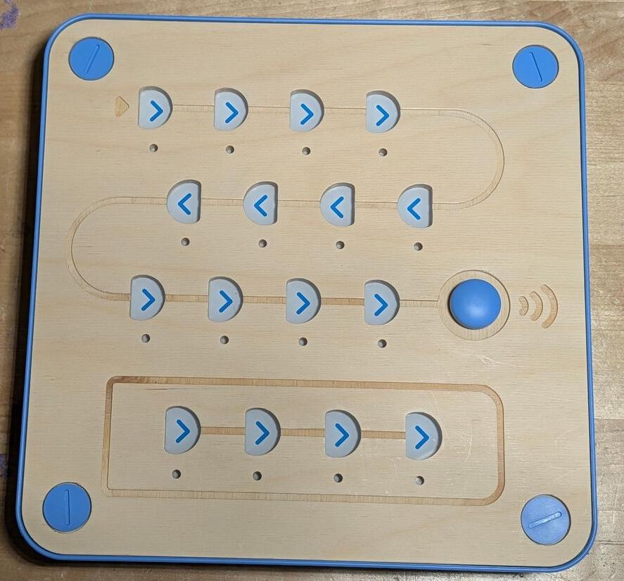
The concept is beautiful: place colored blocks on a physical board to create a sequence of instructions (forward, left, right, function), press go, and the robot follows the program across a playmat. Each page of the included storybooks sends Cubetto from one square to a destination, and the child has to figure out the sequence of moves to get there. It’s Montessori-inspired, tactile, and genuinely clever.
In practice, three things are broken.
The Bluetooth connection between the board and the robot is unreliable. It connects, works for a few sequences, then drops and cycles through reconnection attempts.
The robot consistently fails to execute the last tile in a sequence. Program five moves and the robot runs four. Reproducible. Every time.
And the motor calibration is the worst of all. Turns that should be 90 degrees are severely off, clockwise turns are roughly 20 degrees short, counterclockwise is better but still wrong. Because each page of the story builds on the last, the drift accumulates. By the third or fourth page, the robot is going diagonal, missing squares entirely, and requires manual repositioning to stay anywhere near the grid. For a toy whose entire purpose is deterministic execution of simple instructions, this isn’t a minor issue. It’s fundamentally broken.
Contacting Support
To be fair, they did respond.
I emailed support describing the turning accuracy problem and the last-tile bug, including a video showing both issues clearly. The response blamed the carpet. The surface, they said, was affecting Cubetto’s precision. They also noted that exact precision wasn’t really the goal, this is a toy for young children, after all.
Let me be direct about why that explanation is nonsense.
Cubetto uses stepper motors. The entire point of a stepper motor is precise, repeatable angular displacement. It’s the reason 3D printers, CNC machines, and robotics use them. Surface friction affects whether the wheels grip the floor. It does not affect how many degrees the motor shaft rotates. The carpet is not the problem. The carpet was never the problem.
The problem, as I’d later confirm by opening the robot, is that someone replaced the stepper motor driver with a Darlington transistor array. That decision turned a step-counted precision motor into a time-based guess. The firmware energizes the coils for X milliseconds and hopes the result is 90 degrees. It won’t be. It can’t be. The physics don’t allow it. The motor’s accuracy now depends on battery voltage, temperature, and load, variables that a proper stepper driver eliminates entirely. Blaming the carpet for a problem caused by swapping a stepper driver IC, a part that costs somewhere between $0.25 and $0.50, for a $0.15 Darlington array is either ignorance or deflection. Given that the company has two employees and operates through a white-label support contractor, I’m guessing nobody left in the building knows what a ULN2803G is or why it doesn’t belong anywhere near a stepper motor.
And if exact precision truly isn’t the goal, then why are there stepper motors in this thing at all? A pair of cheap DC geared motors would be equally imprecise and cost a fraction of the price. The steppers are there because the original design was precise. The original founders chose them for a reason. The new owners just removed the part that made them work.
After some back and forth, they agreed to send a replacement control board. Credit for that. Whether a new board fixes the turning accuracy issue remains to be seen, since that’s a robot-side problem, but at least they’re willing to try.
Some context on who I was actually talking to: Primo Toys was acquired at some point by EET Group, a European electronics distributor. The operation now runs out of Brno, Czech Republic. Based on LinkedIn, the company appears to have approximately two employees. My first support email was answered by an automated four-language autoresponder from “Moravia Consulting” that addressed me as “Business Partner.”
But I’m getting ahead of myself. I didn’t know any of this yet when I contacted support. To understand what actually went wrong, I had to open it up.
Opening the Robot
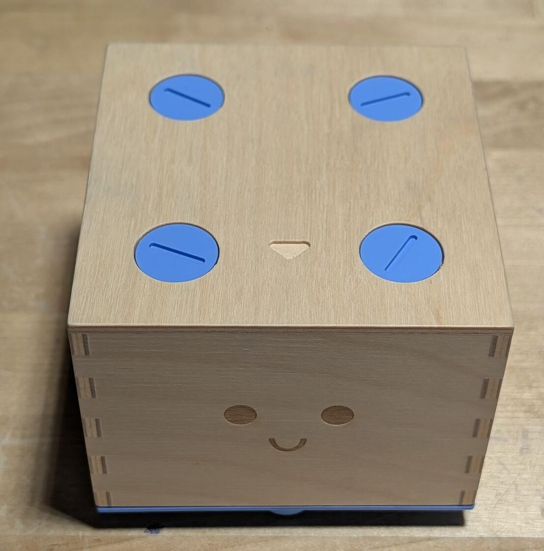
Four large blue screws on the top, removable with a coin. Clearly designed to be opened, which is ironic given what I found inside.
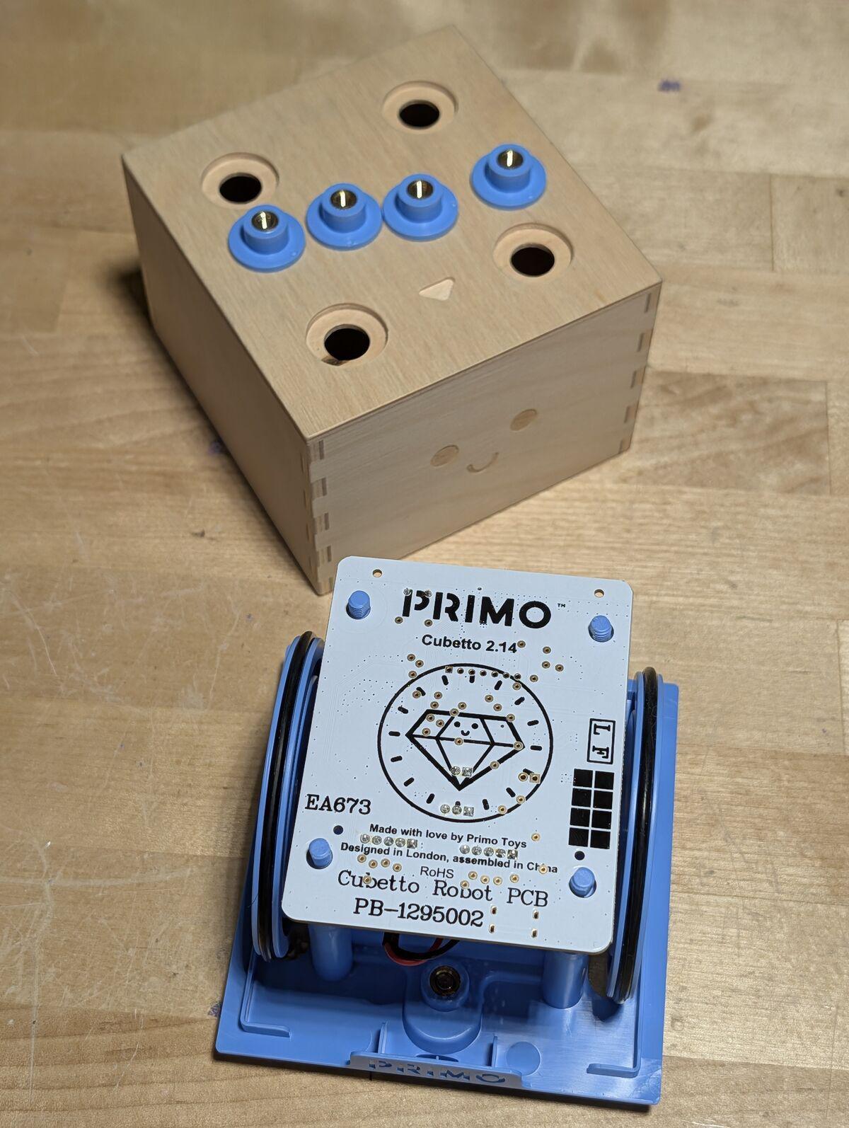
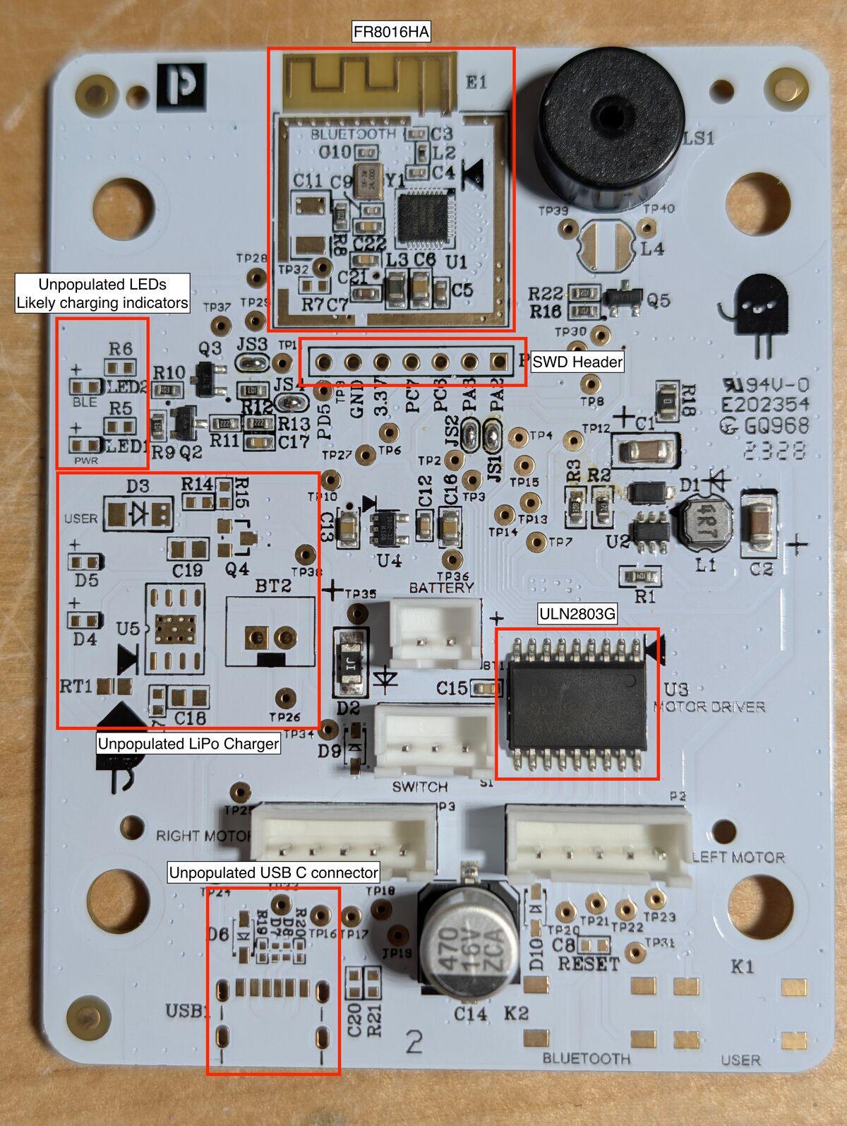
The Robot PCB
The back of the board says version 2.14.
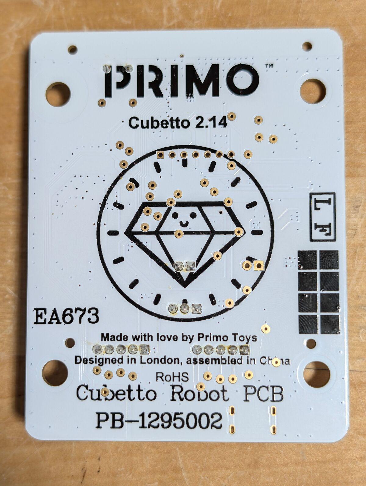
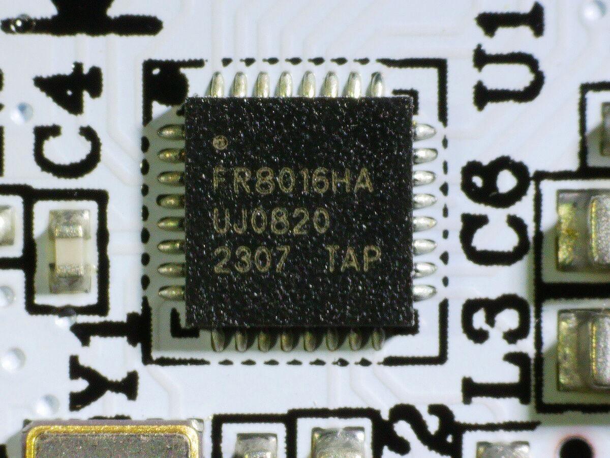
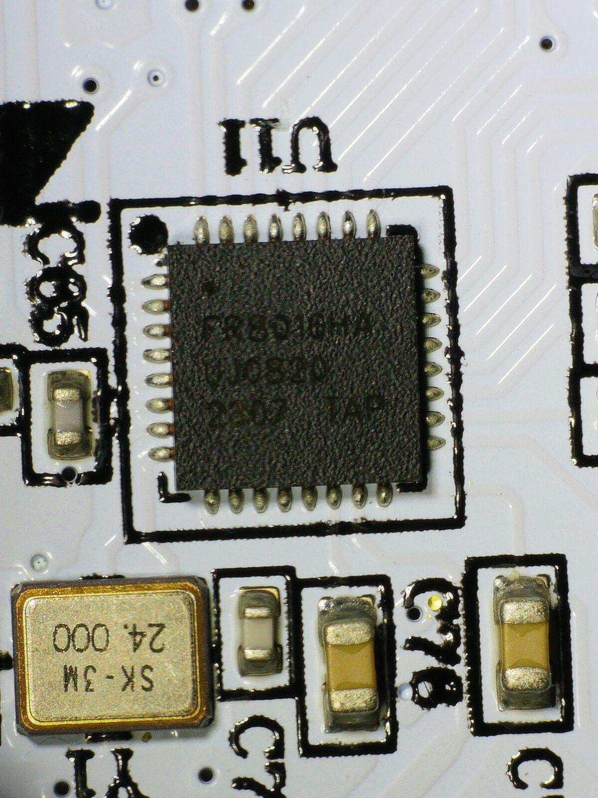
Flipping it over tells the real story. The brain is an FR8016HA, a Freqchip ARM Cortex-M0 BLE SoC. If you haven’t heard of Freqchip, you’re not alone. It’s a budget Chinese BLE chip with no public SDK, no community, and essentially no documentation outside of whatever Freqchip provides to direct customers. This is about as far from the Arduino ecosystem as you can get, and that matters, because the original Cubetto was Arduino-based. But I’ll get to that.
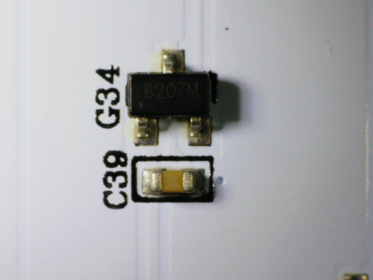
I pulled out the microscope to read the chip markings.
Next to the SoC sits the ULN2803G Darlington transistor array I mentioned earlier, labeled “MOTOR DRIVER” on the silkscreen. It is not a motor driver. It’s a transistor switch array from the 1980s designed to sink current for relays, solenoids, and indicator lamps, and it’s what replaced the proper stepper driver that made the original Cubetto work.
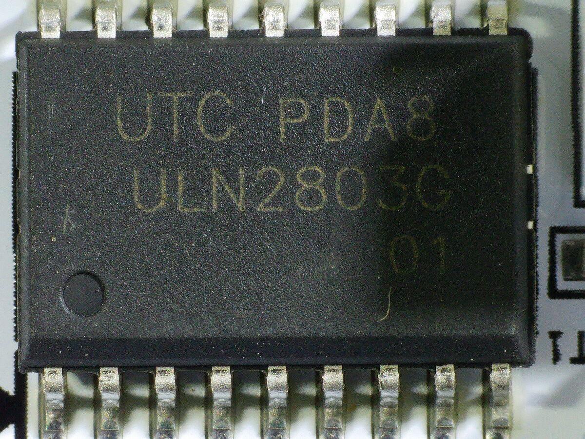
Why keep the stepper motors but swap out the driver? Because the motors are molded into the plastic housing. Retooling injection molds costs tens of thousands of dollars. Swapping a driver IC saves a few cents per unit and requires zero mechanical changes. So the steppers stayed. The stepper driver did not. You paid for stepper precision and got Darlington slop.
The PCB also has an unpopulated SWD debug header at P1 (PA2/PA3), the only realistic path for firmware updates on this chip. Without an ST-Link or a debug probe, there’s no way to touch the firmware.
The Firmware Update That Doesn’t Exist
Cubetto’s official support documentation includes a video showing a firmware update process via USB. The board in that video is a completely different design: Arduino hardware, a separate Bluetooth module, physical buttons, and a mini USB port. A white PCB with blue silkscreen, also marked 2.14, but with every label carefully placed to avoid vias. A different board from a different era wearing the same version number.
There’s an even more revealing video I found buried in the Wayback Machine, since marked private on YouTube, titled “How to fix Cubetto’s turning angle.” It opens by demonstrating the exact problem I’m experiencing: the robot doing a couple of turns, an overlay showing the angle deviation from 90 degrees, the error accumulating with each turn, the robot drifting off the path during forward motion. They knew about this problem.
The fix? Download the Arduino IDE, open a provided sketch called PrimoCubettoOOBExample.ino, and install the Genuino Zero board through the Arduino Board Manager, confirming that the original PCB was built on the SAMD21 (ARM Cortex-M0+), the same chip as the Arduino Zero. Then add two libraries via zip: AccelStepper.h and CubettoLibrary.h. AccelStepper is a proper step-counting stepper motor library, confirming the original design used an actual stepper driver IC, not a Darlington array.
The video instructs you to open CubettoLibrary.h in a text editor. The header exposes several constants (STEPPER_MAX_SPEED, STEPPER_ACCELERATION, STEPPER_FORWARD_STEPS, STEPPER_TURN_STEPS) but the only one you’re asked to change is STEPPER_TURN_STEPS. A slide reads “One degree = 12 steps.” For the demo, the value is set to 1120 (93.3°) to exaggerate the error, and the fix reduces it to 1060 (88.3°). For what it’s worth, 90° at 12 steps per degree is exactly 1080, and neither value is that.
But here’s what matters: on the original hardware, you could fix this yourself. Open the robot, plug in USB, adjust a constant, upload. The stepper driver counted actual steps. AccelStepper handled acceleration profiles. The calibration was off but the mechanism was sound.
My robot can’t do any of that. Despite sharing a version number with the board in those videos, they have almost nothing in common. The Arduino hardware is gone. The separate BT module is gone. The buttons are gone. AccelStepper is gone. And where the old design had a mini USB port, my board has a USB-C footprint, pads laid out, silkscreen marked, but the connector is unpopulated. There is no physical way to update the firmware through the documented process. The documentation references a board that no longer exists.
Opening the Control Board
The control board is built in layers. Four screws get you in, and each layer peels back something about how the tile detection works.
Under the plywood tile tray sits a plexiglass overlay with blue chevron arrows printed on it, one per tile slot, showing the direction each tile faces when inserted.
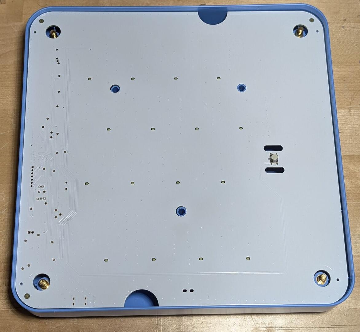
Remove the plexiglass and the PCB is fully exposed.
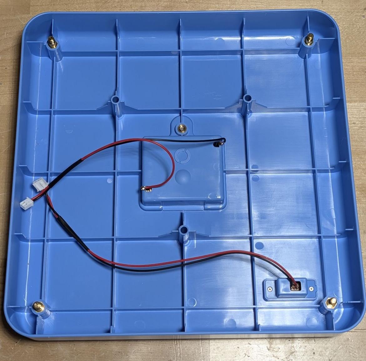
The housing underneath holds the battery compartment and wiring harness.
Hall Effect Sensors, Not NFC
I assumed the tiles would use NFC or RFID, some kind of wireless identification. What I found instead were HM6207 hall effect sensors. Three per tile slot, arranged in a triangular pattern, spaced far enough apart that a single magnet in a tile can only trigger one sensor at a time.
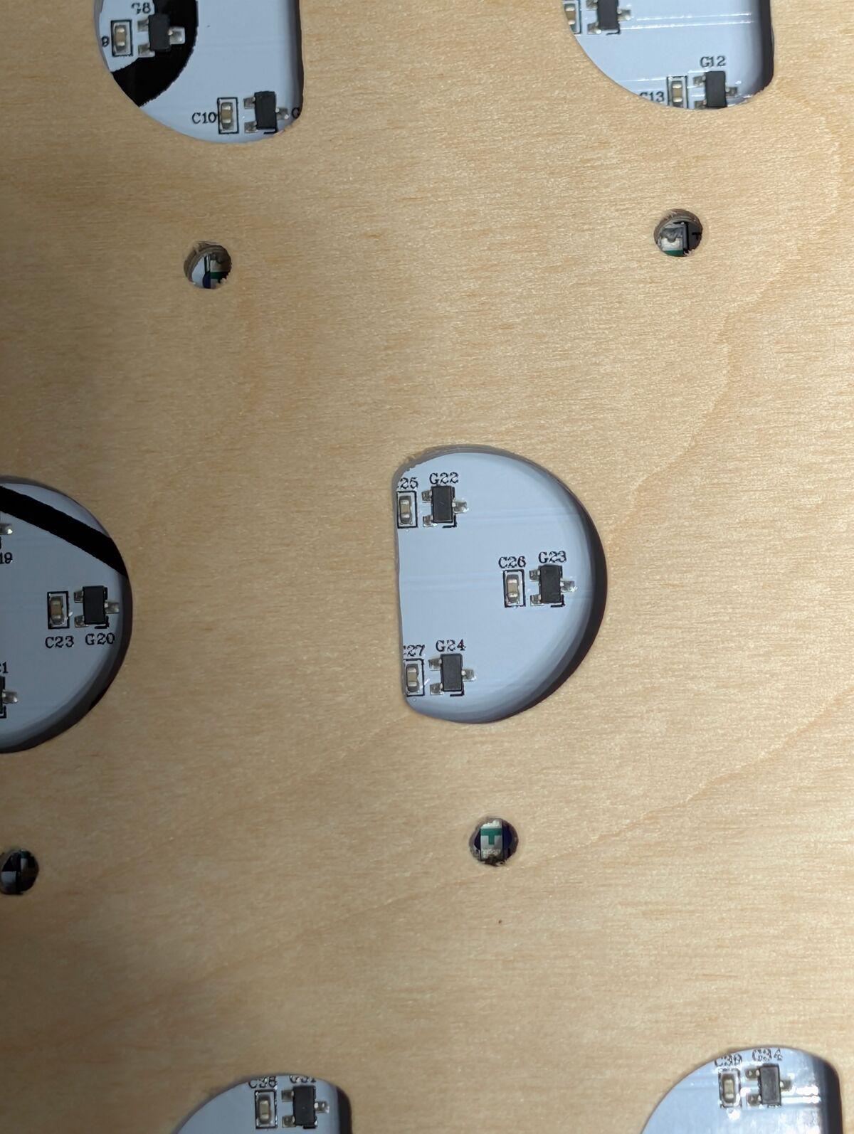
The tiles don’t contain electronics at all. They contain small magnets, positioned to activate specific combinations of the three sensors. Three sensors gives you 2³ = 8 possible states minus one (no magnets = empty slot), leaving 7 detectable states.
The Cubetto I bought ships with 4 tile types: forward, left, right, and function. The function tile is the blue one, and it’s clever: the control board has a separate bottom row (the function row) where you can place a sub-sequence of moves. Every blue tile in the command rows triggers the entire function row once, so you’re effectively teaching subroutines to a three-year-old.
With two sensors you’d get 2² - 1 = 3 usable states (excluding empty), which covers forward, left, and right. But the function tile pushes you past three, so you need a third sensor. Three sensors gives you 7 possible states, not 4. Three of those states are unused in the Cubetto I bought. I’ll come back to why.
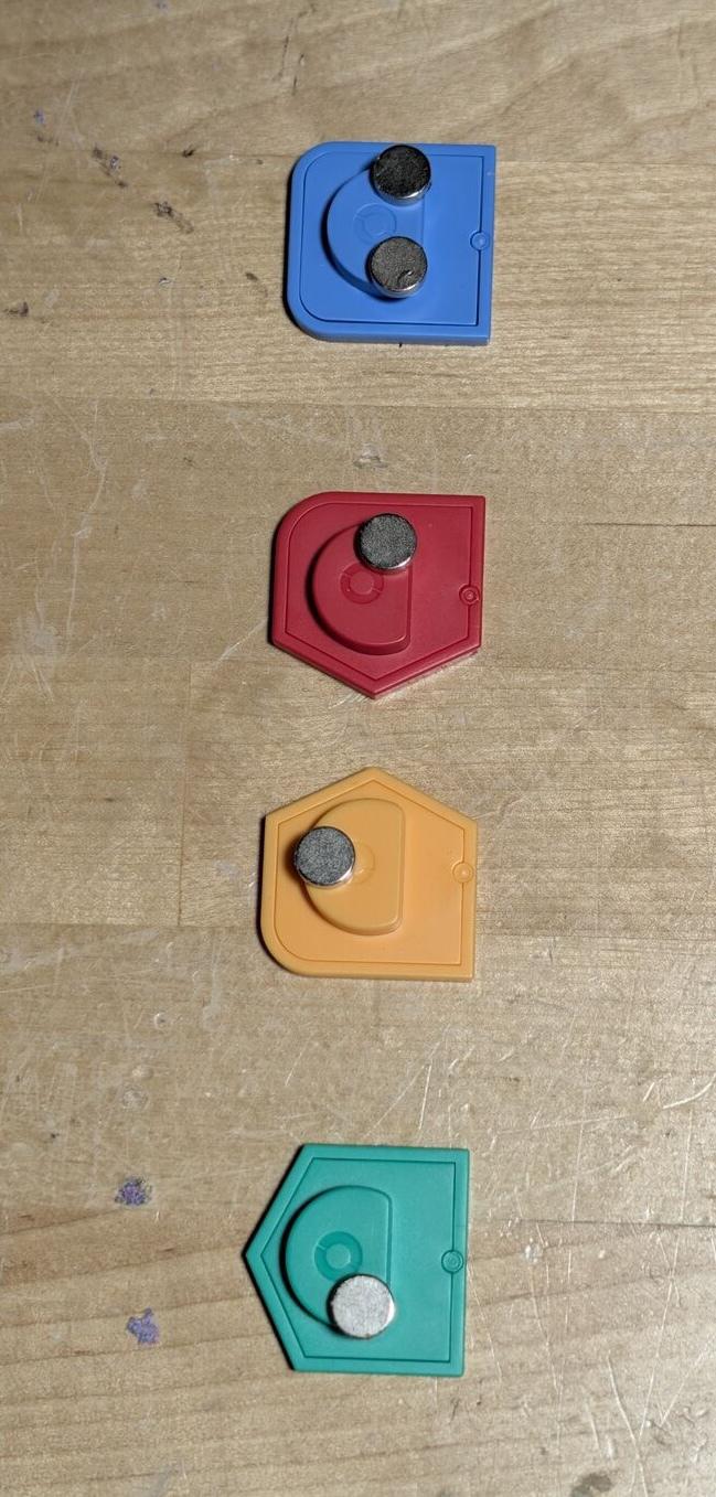
Regardless, the encoding is genuinely smart. No electronics in the tiles means no batteries to die and no moving parts to wear out. Just magnets and physics.
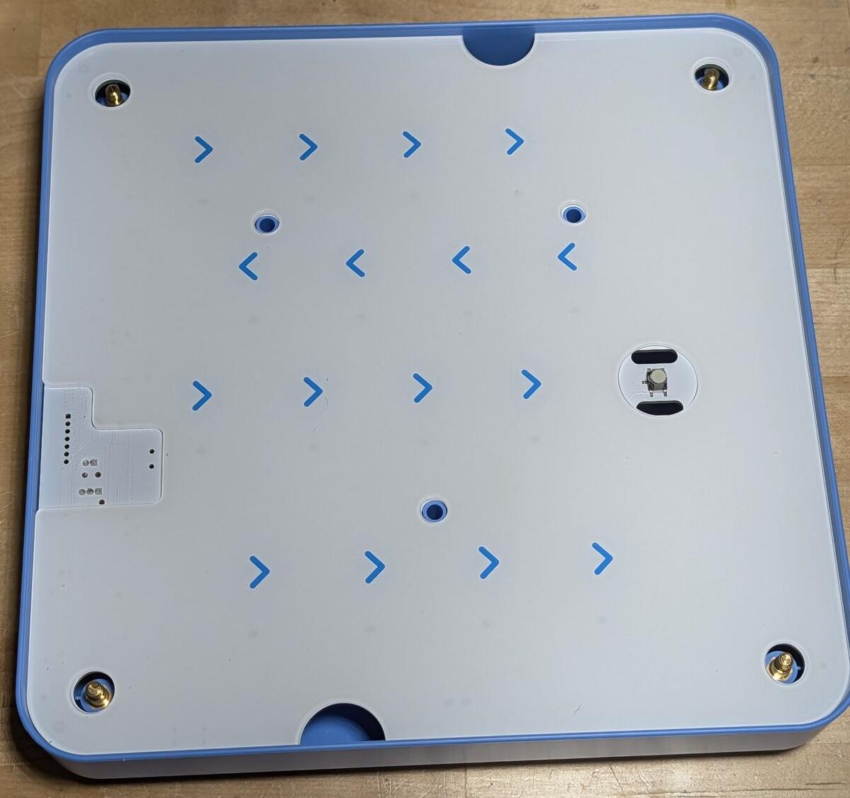
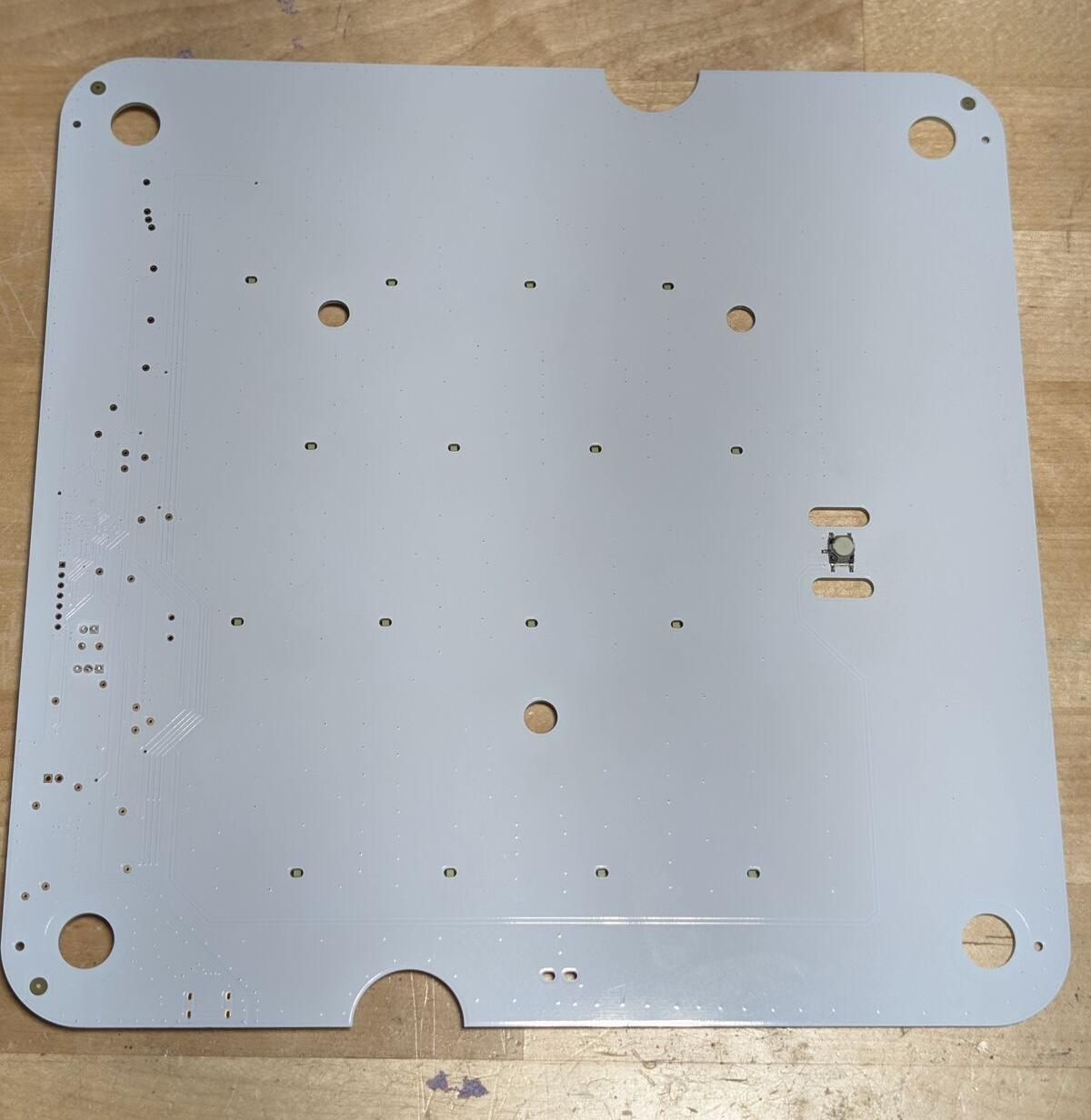
The Control Board PCB
The front of the PCB is sparse, just the Go button and an array of holes where LEDs shine through to indicate tile status.
The back is where everything lives. And the first thing I noticed: this board is marked version 2.19. The robot is 2.14. That’s a version mismatch between the two boards that are supposed to talk to each other over Bluetooth. If the communication protocol or command format changed between revisions, this could explain the last-tile bug, the BT dropouts, or both. There’s no way to know without the firmware source, but shipping mismatched board revisions in the same box isn’t exactly confidence-inspiring.
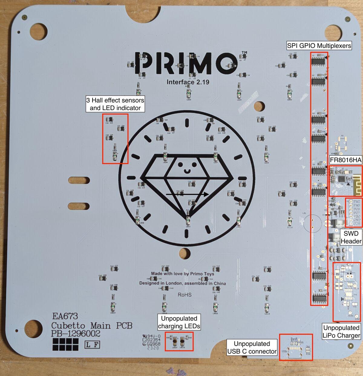
Putting the control board under the microscope, same FR8016HA as the robot, with a 24 MHz crystal next to it.
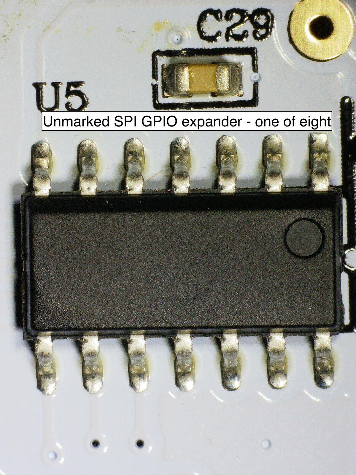
Eight identical unmarked 14-pin ICs multiplex the hall effect sensors and LEDs, two per row across the board’s three command rows and one function row. Each IC handles two tiles (6 hall effect sensors + 2 LEDs) over a shared 3-wire bus with individual chip selects to the MCU.
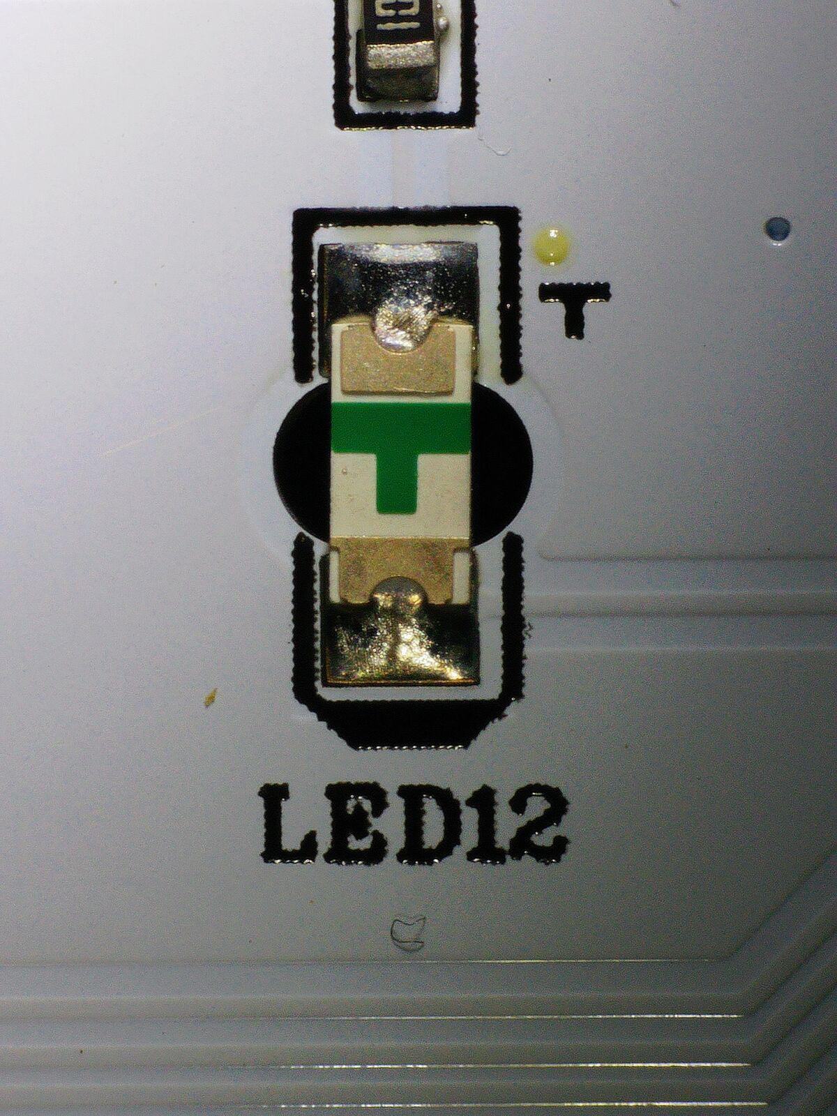
The single-color SMD LEDs sit on the back of the board and shine through holes in the PCB.
The Cubetto+ Connection
Across both boards, the pattern is the same: unpopulated USB-C connectors, LiPo charging circuits with thermal management pours, protection FETs, battery connectors, charging indicator LEDs, solder jumpers, and test points. All designed in, all silkscreened, all empty.
Version 2.19 isn’t a Cubetto board. It’s a Cubetto+ board with half the components left off. The same is true for the robot’s 2.14, unpopulated Cubetto+ footprints everywhere. Cubetto+ is the newer version of the product that adds three tile types (backwards, stop, and random), bringing the total to 7, which is exactly the number of states the hall effect sensor matrix was designed for. Remember the three unused states from earlier? This is where they went.
Primo’s own site only lists the Cubetto+ now; the regular Cubetto appears to be discontinued. Third-party retailers like RobotShop still have old stock (33 units when I checked) with the Cubetto+ expected to restock by March 18, 2026. What I received is a Cubetto+ board with the charging circuit unpopulated, three tile types withheld, and solder jumpers set to the cheaper variant. One PCB design built for the product they’re transitioning to, shipped as the product they’re phasing out.
The version numbers are misleading in the other direction too. The firmware update video on YouTube shows a board also marked 2.14, but it’s an entirely different design, white PCB with blue silkscreen, labels carefully placed to avoid vias. My 2.14 is white with black silkscreen and no such care taken; text falls across vias and gets clipped. Same version number, different board, different era.
A Note on the LiPo
Cubetto+ adds a rechargeable LiPo battery, which sounds like a nice upgrade until you think about who actually uses this product.
Saturday morning after breakfast. Your kid says “Daddy, I want to play with the robot.” When did you last use it? Two weeks ago. Maybe three. You check the battery. Dead. Of course it’s dead. LiPo self-discharge plus a three-year-old’s usage patterns guarantee it. “Sorry honey, the robot needs to charge first.” Minimum two hours. By the time it’s ready, the kid has moved on to something else entirely. The window is gone.
Four AA batteries are always ready. They last for months in a toy that gets used in sporadic bursts. Swapping them takes ten seconds. They’re available at every corner store on earth.
The LiPo is an engineer-brain decision made by someone who doesn’t have kids, or at the very least, a checkbox exercise to claim “rechargeable” and “eco-friendly” on the product page. In practice, it makes the toy less available to the child at the exact moment the child wants it. That’s a worse product disguised as a better one.
What I’m Doing About It
I could try to hack the firmware. The SWD header pads are accessible and the Cortex-M0 is a well-understood architecture. But reverse-engineering proprietary firmware on an undocumented SDK for a BLE SoC with no community is a time investment I can’t justify. I didn’t have time to break out the Bus Pirate or the ST-Link for what should be a functioning children’s toy.
Instead, I’m designing replacement PCBs for both the robot and the control board.
The design targets:
- ESP32-C3 for both boards. BLE 5.0 plus WiFi for OTA updates, Arduino IDE compatible, costs about $2 per module
- Proper stepper motor driver replacing the ULN2803G, restoring the step-based precision these motors were designed for
- SK6812 RGBW LEDs replacing the original single-color LEDs, enabling visual feedback during program execution, completion animations, error indicators, and whatever else the firmware dreams up
- Populated USB-C and SWD headers, because firmware update ports should exist on hardware that documents firmware updates
- Same hall effect sensor matrix architecture, the 3-bit triangular encoding scheme is actually clever, and the physical tiles don’t need to change
The goal is a drop-in replacement that uses the original wooden enclosure and tiles but fixes everything that’s broken about the electronics. Open firmware, open hardware, and a product that actually works the way the marketing says it does.
Distribution will be through Tindie with boards assembled by JLCPCB, PCBWay, or your preferred PCB manufacturer. One Hackaday post. No Kickstarter, no marketing campaign, no influencer strategy. Just boards that work, documentation that’s honest, and the source files published for anyone who wants to spin their own.
Why This Matters
My kids deserve better than a Bluetooth connection that drops, a robot that skips instructions, and turns that drift further off course with every page of the story.
The original Cubetto promised something beautiful, a child’s first encounter with programming logic that’s tactile, immediate, and reliable. Place a block, press a button, watch the result. Cause and effect. Deterministic systems. The foundation of computational thinking.
Somewhere between the Cannes Lion and the acquisition, that promise got cost-engineered into a product that can’t execute its own programs reliably. The founders walked away. The acquirer doesn’t care. The documentation still references hardware that no longer exists.
That promise is still worth keeping. Since nobody else is going to build it, I guess that’s what the workshop is for.