Disclosure: English is my third language and I can’t write for shit in any of them. I used AI to help me write this post. The research, teardown, reverse-engineering, and every technical finding here are entirely mine. The AI helped me say it without making your eyes bleed. If you’d rather argue about prose than NFC antenna multiplexing, this isn’t the post for you.
I bought into the Pura ecosystem the way everyone does. The app is slick, the scents are genuinely nice, and the hardware looks like it fell off an Apple truck. Then I saw what a replacement cartridge costs, watched the whole thing go dark the moment the cloud sneezed, and did what I always do — I opened it up.
What I found is a masterclass in how not to build a connected product. The diffuser is an ESP32 with no secure boot and no flash encryption. Its per-device AWS IoT private key sits in plaintext in the NVS partition, readable in about five minutes with a USB-serial adapter. The “authenticity” of the fragrance cartridges is a signed URL on an NFC tag that means nothing until a cloud endpoint blesses it — and the depletion counter that declares a cartridge “empty” is enforced entirely in software.
By the end of this I had two different Pura models — a Pura Plus and a Pura Wall V4 — running local ESPHome firmware, dual-bay NFC reading working (which the community driver didn’t support yet), heaters regulated so they don’t cook themselves, status LEDs, per-bay timers, and zero cloud dependency. This post is everything I found, top to bottom.
The lineup
There are several Pura models, and they are not the same board:
- Pura Mini / Pura 4 — the wall-plug models. A community ESPHome component already exists for these.
- Pura Plus — the vertical tabletop tower. USB-C powered, two cartridge bays, two WS2812 LEDs, two mechanical push buttons, a fan.
- Pura Wall V4 — a newer wall unit. Mains-powered through a non-isolated AC/DC switcher, six-LED ring, single button, two bays on pogo-pin NFC antennas.
The Plus and the Wall had no local firmware support at all, and dual-bay NFC was unsolved everywhere. That gap is most of what this writeup fills.
All of them are built on the same module: an ESP32-WROVER-E, dual-core, 8 MB flash, running an ESP-IDF application. The firmware codename even leaks _dvt — a development-verification-test string — on shipping retail units.
And critically: no secure boot, no flash encryption. That single decision is the whole story.
Step 1 — Getting the firmware out
Open the case and you’ll find an unpopulated header with the usual suspects broken out: TX, RX, GND, GPIO0, 3V3. A full serial-download interface, handed to you for free.
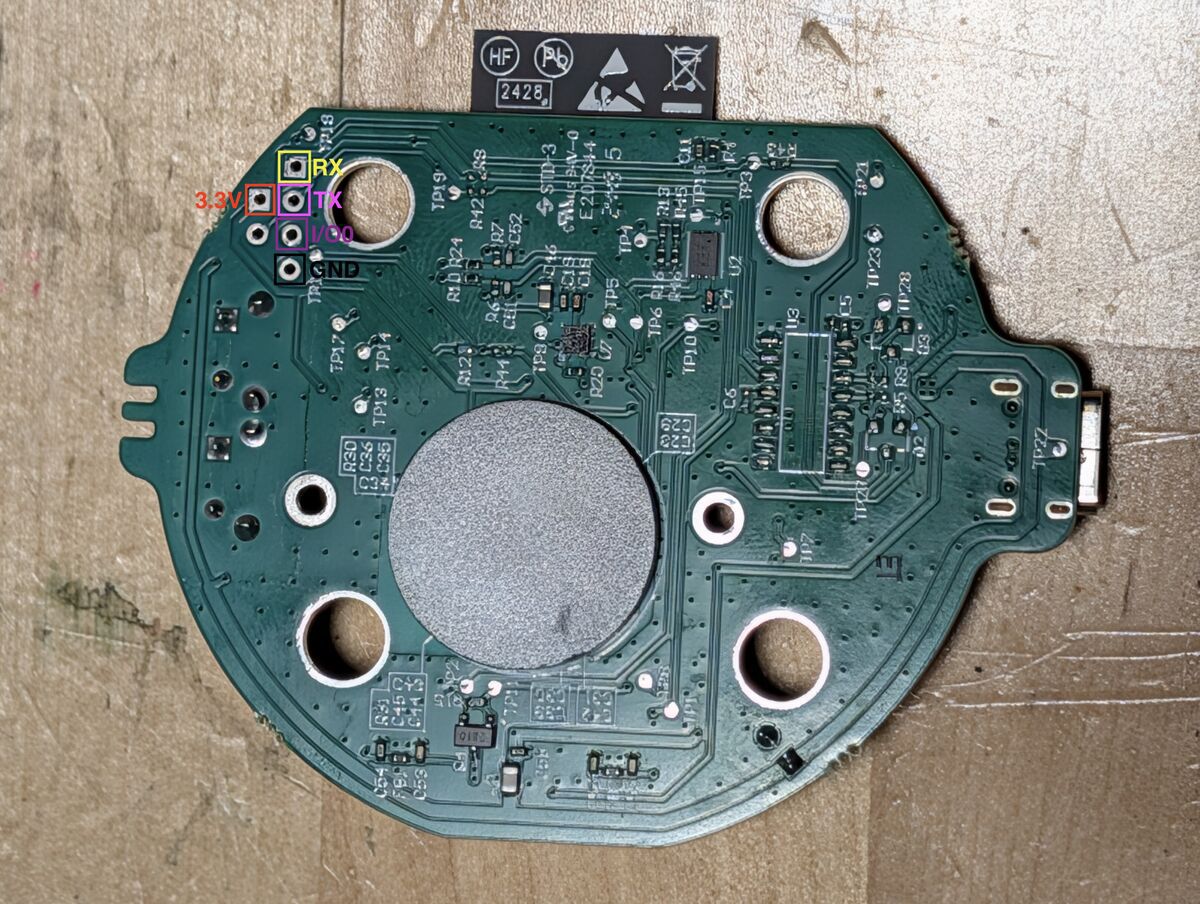
The ESP32 drops into its serial bootloader when GPIO0 is held low at reset. There’s no auto-reset circuit wired to the adapter’s DTR/RTS on these boards, so esptool can’t toggle the chip into the bootloader for you. Two things matter:
- Pull GPIO0 to GND manually while power-cycling to enter download mode. (Don’t solder it to ground and forget — the app won’t boot with GPIO0 tied low. Ask me how I know.)
- Tell esptool not to try resetting:
--before no-reset. And keep the baud at 115200 — anything faster corrupted the transfer on my adapter and left the ROM loader wedged until a power cycle.
Then just read the whole 8 MB out:
esptool.py --before no-reset --baud 115200 read_flash 0x0 0x800000 dump.bin
Because there’s no flash encryption, dump.bin is the real thing — bootloader, partition table, app, and NVS, all in cleartext.
Back up every unit before you flash anything. Each device’s dump contains its unique cloud credentials; if you ever want the thing to talk to Pura again, that dump is the only copy.
Step 2 — Reading the flash: the keys are just… there
The interesting part lives in the NVS (non-volatile storage) partition. On these images the partition table sits at 0x10000 and the nvs partition starts at 0x11000. Parse the NVS blob — it’s a documented ESP-IDF format, key/value entries in 32-byte slots with larger values chunked into blob pages — and out fall, in plaintext:
- The device’s AWS IoT client certificate
- Its RSA private key
- The root CA it trusts
A per-device identity for a production AWS IoT endpoint, extractable by anyone with physical access and a $3 cable. No attestation chip guarding it, no key wrapping, nothing.
One detail you’ll need if you ever want to write NVS back (I did, later, to MITM the cloud): each NVS entry carries a CRC, and so does each blob-data page. Both use the same construction — a standard CRC-32 over the relevant fields with an initial value of 0, then XORed with 0xFFFFFFFF:
crc = crc32(fields, init=0) ^ 0xFFFFFFFF
Get that formula right and you can rewrite any NVS value — a WiFi SSID, a trusted CA — and the firmware accepts it as genuine.
Step 3 — MITMing the cloud
Before ripping the cloud out, I wanted to watch it. How does the diffuser actually talk to Pura?
- Transport: MQTT over TLS 1.2, on port 443, using ALPN
x-amzn-mqtt-ca. That ALPN string is the tell — it’s AWS IoT’s pattern for muxing MQTT onto 443 so it survives restrictive networks. - Broker: a vendor-branded AWS IoT endpoint (
mqtt.aroma.trypura.io). - Auth: mutual TLS with the per-device cert/key we just pulled out of NVS.
To sit in the middle, I:
- Redirected DNS for the broker hostname to my own box (any local resolver that lets you override a record works).
- Ran a transparent mTLS relay — listen on 443 presenting a server cert for the broker’s CN, and connect upstream to the real AWS endpoint using the device’s own extracted cert and key.
A few things fought me, and they’re worth writing down because they’ll bite anyone doing this:
- The AWS broker rejects TLS 1.3. The upstream leg has to be pinned to TLS 1.2 or the handshake dies with an unexpected-message alert.
- On the relay’s own listener, verification has to be disabled (
CERT_NONE) — you’re impersonating the endpoint on purpose. - Don’t thread the SSL sockets. A naive thread-per-direction relay corrupted the TLS streams; a single-threaded
select()loop pumping both directions was rock solid. - The device won’t trust your relay’s certificate — it throws an
UNKNOWN_CAalert, because it only trusts the exact root CA baked into its NVS. This is where Step 2’s CRC formula pays off: patch the device’saws_root_caNVS value to your MITM CA, recompute the NVS CRCs, write it back. Now the device happily hands you its plaintext MQTT session.
With the traffic in the clear, the control protocol turns out to be small and obvious. Heating a bay is a short binary command — a fixed opcode followed by a per-bay intensity byte, 0xFF meaning “on” — and the cloud only ever drives one bay at a time, never both coils together (a power budget, I’d guess; more on that at the heaters).
Step 4 — The cartridge “DRM” is a cloud opinion
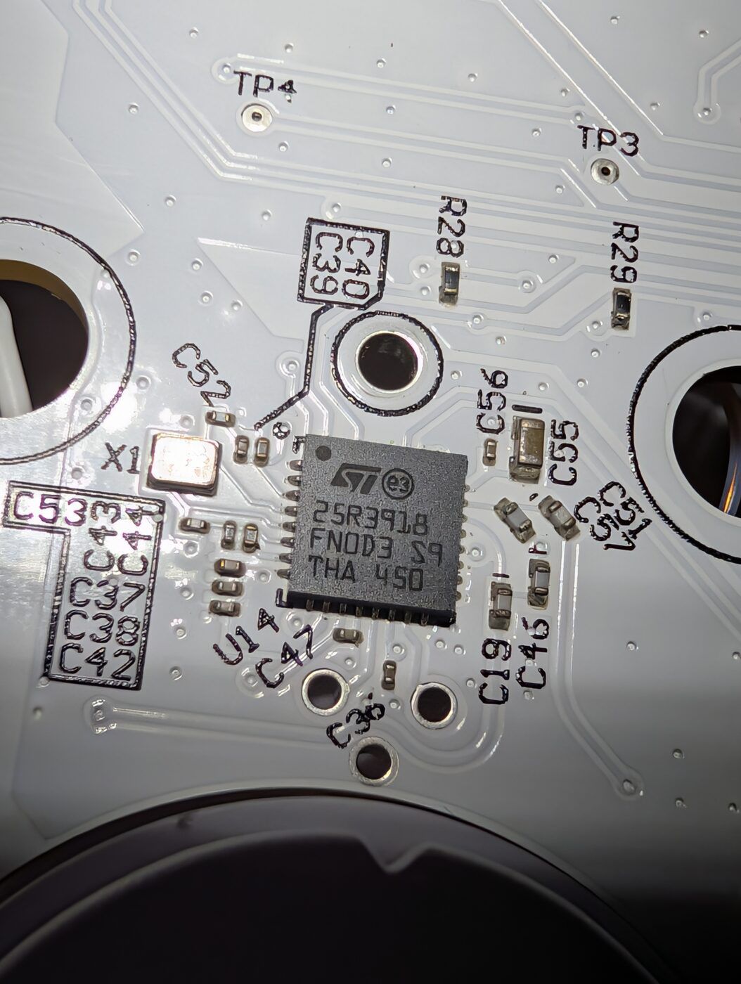
Each fragrance cartridge carries an NFC tag read by an ST25R3918 (an ISO 15693 / NfcV front end from ST). The tag isn’t encrypted data — it’s a signed URL. Roughly:
pura.com/ss?d=<tag-UID>.yyy.<8-byte keyed MAC>
The tag UID plus a short keyed MAC. The device reads it, ships the token up to the cloud, and the cloud decides whether the cartridge is “genuine” and how much scent is “left.” Two consequences fall straight out of that:
- Authenticity is a server call. The cartridge doesn’t prove anything cryptographically to the device; it proves it to Pura’s backend. Which means a fake backend — or a liberated device that simply never asks — can answer “genuine, full” every single time.
- Depletion is soft. The “you’re out of scent” state is bookkeeping enforced in the app and cloud. Locally, a cartridge the app calls empty still heats and still diffuses when you command the bay directly. There’s fragrance oil left; the counter just decided you were done.
That soft depletion is the whole reason I started down this road. You can refill a cartridge — pop the wick out, top it up with a dropper, drop it back in — and today the cloud will happily keep heating it long past zero. That’s not generosity: the “amount remaining” is a rough estimate, and Pura would rather over-serve than field complaints about paid-for oil going to waste. Fine by me.
But look how fragile that is. The heater is cloud-driven — you press the button in the app, and a server decides whether the coil warms up. So the whole refill path survives entirely at Pura’s discretion. One flag — refuse to heat a cartridge the backend calls empty — and every refilled cart in the world goes cold overnight, no matter how much oil is actually in it. Run it locally and that switch doesn’t exist: a refilled cart heats because I said so, and no server gets a vote.
Here’s the kicker. Sitting on the Plus’s I²C bus is an Atmel/Microchip ATSHA204A — a genuine crypto authentication chip, symmetric SHA-256 challenge/response, the exact part you’d use to do offline cartridge authentication that a fake cloud couldn’t spoof. It’s populated on the Plus board (the Wall doesn’t seem to carry it). It responds on the bus (you can wake it and get the classic 04 11 33 43 back). The firmware never uses it. They paid for the lock and never fitted it to the door.
Step 5 — Bringing it up on ESPHome
This is the liberation. The goal: full local control, no cloud, dual-bay NFC, and heaters that don’t set anything on fire.
Pin maps
The two board families differ, so here are both. (Thermistors and the NFC IRQ happen to line up; almost nothing else does.)
Pura Plus (tabletop, USB-C):
| Function | GPIO |
|---|---|
| Heater — left / right | 12 / 13 |
| Thermistor ADC — left / right | 36 / 39 |
| Fan | 14 |
| LEDs (2× WS2812) | 21 |
| Buttons — left / right | 15 / 4 |
| NFC I²C — SDA / SCL / IRQ | 18 / 5 / 27 |
| Accelerometer INT | 26 |
| Board-revision divider | 34 |
Pura Wall V4 (mains):
| Function | GPIO |
|---|---|
| Heater — left / right | 22 / 23 |
| Thermistor ADC — left / right | 36 / 39 |
| Fan | — (heat-only, no fan) |
| LEDs (6× WS2812 ring) | 25 |
| Button | 4 |
| NFC I²C — SDA / SCL / IRQ | 33 / 32 / 27 |
| Board-revision divider | 34 |
On the Plus, the I²C bus carries three devices worth naming:
0x19— LIS2DW12 accelerometer (WHO_AM_Ireturns0x44) — almost certainly a tip-over / orientation guard, there to cut the heater if the unit gets knocked over.0x36— the ATSHA204A crypto chip from Step 4, present-but-unused (the Wall board doesn’t carry it).0x50— the ST25R3918 NFC reader.
The board-revision trick
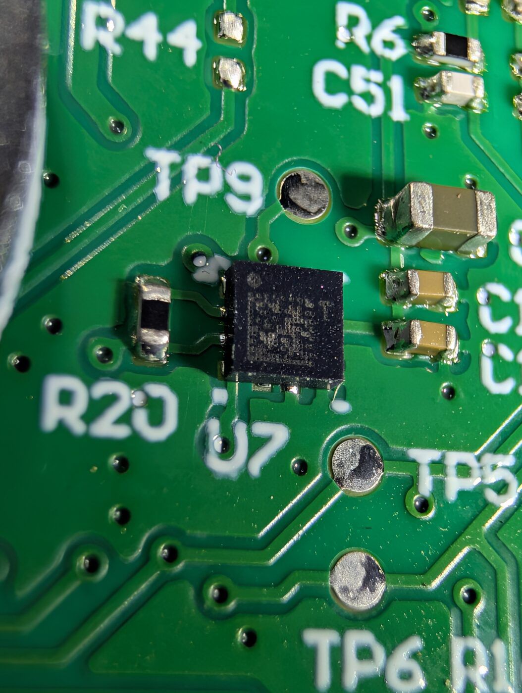
GPIO34 reads a resistor divider whose voltage encodes the board/model. Different models sit at cleanly separated voltages (on my units, two families landed near ~0.14 V and ~0.81 V). A single ADC read at boot is enough for the firmware to announce which model it’s running on — handy when you flash one codebase across a fleet.
Dual-bay NFC — reading both cartridges
Both two-bay models have two separate antennas, one per cartridge slot, wired to a single ST25R3918. Every existing driver only ever read one. The datasheet buries the answer in a single line: the ST25R3918 transmitter can drive RFO1 and RFO2 independently, i.e. two single-ended antennas.
You switch between them by writing the IO Configuration Register 1 (register 0x00). The trap that cost me an evening: setting the rfo2 bit is not enough. In the default differential driver mode, rfo2 is a no-op. You have to set both the single-ended-mode bit and the rfo2 bit together:
// Select which single-ended antenna (bay) is live.
// BOTH bits: single-ended mode (bit7) AND rfo2 (bit6). Setting rfo2 alone
// does nothing while the driver is still in differential mode.
uint8_t mask = REG_IO_CONF1_single | REG_IO_CONF1_rfo2;
uint8_t val  = REG_IO_CONF1_single | (bay ? REG_IO_CONF1_rfo2 : 0x00);
reader.changeRegisterBits(REG_IO_CONF1, mask, val);
With that, the pattern is: pick an antenna, run a discovery cycle, record what (if anything) that bay saw, flip to the other antenna, repeat. Alternate roughly once a second and give each bay a short presence timeout — if an antenna goes a few seconds with no tag, that bay is empty, which is exactly the signal you want to surface. Suddenly both slots report their own cartridge independently. Install two different scents and each bay knows which is which.
If you install two cartridges and read them on a single, un-switched antenna, you get a classic collision — either one tag shadows the other or the reader sees nothing at all. That symptom is the giveaway that antenna switching is the missing piece.
Worth being clear here: I didn’t start from scratch. A community project — TheFatBastid’s Local-Pura — had already done the hard groundwork: found the programming pads, ported the ST25R3918 driver (from ST’s RFAL library), and gotten the single-bay Pura Mini and Pura 4 running fully local. That’s what I flashed first, and it’s the reason this was a weekend and not a month.
What it didn’t cover was the two-bay models. So I cleaned a few things up and added the missing pieces — the RFO1/RFO2 antenna switching so both bays read independently, the full Pura Plus pinout, and what GPIO34 actually does (the board-revision divider the original author had flagged as “unknown”) — and sent it all back upstream: dual-bay support in the driver, plus ready-to-flash Plus and Wall V4 configs. Their work made mine easy; this just adds the next layer so the person after me has less to figure out.
Heaters: don’t trust the thermostat
The diffuser works like any plug-in scent or mosquito vaporizer: a circular ceramic heater warms a thick cotton-blend wick, the fragrance oil climbs the wick by capillary action, and the heat evaporates it off the top. Hotter wick, stronger scent. Intensity (“Subtle / Medium / Strong”) is just a target temperature, closed-loop — not a raw duty cycle. On these boards the targets land around 55–80 °C depending on model and setting.
Which brings me back to that one-bay-at-a-time rule from the MITM — and it was the cloud’s rule, not the hardware’s. The two heater lines are fully independent; nothing on the board stops you from driving both at once. My ESPHome build copies the one-at-a-time behavior anyway, as a deliberate interlock, but only because I’m guessing at a power budget: two ceramic coils flat out would probably pull more than the supply is sized for, and I’d rather not let the magic smoke out to find out. Drop that interlock and you’d have a free boost mode — two carts of the same scent, both coils at max, to flood a room fast. The cloud would never let you. Locally, it’s one line.
My first attempt used a stock-style PID/thermostat control loop. On one bring-up it overshot to 114 °C because the target never actually got applied and it merrily drove the heater to its visual limit. On a mains-powered unit, that is not a bug you want.
So I threw it out and wrote a dumb, auditable bang-bang regulator in a 1-second interval loop instead:
if (heating) {
  float t = temperature();          // median-filtered thermistor
  if (isnan(t))            heater_off();               // sensor gone -> fail safe
  else if (t >= HARD_MAX) { heater_off(); bay_off(); } // hard cutoff (85–90 °C)
  else if (t < target - 1) heater_on();
  else if (t > target)     heater_off();
}
Two hard-won details:
- Verify your units before you blame the hardware. For a while I was convinced the thermistor was throwing wild spikes — my dashboard flashed 138 right as the heater cut, on a surface I knew was about 59 °C. It wasn’t noise. The device reports Celsius; my dashboard was set to Fahrenheit, and 138 °F is 58.9 °C — the correct reading. On the device side the values were clean the entire time. I still run a median filter (window of 9 over a fast 100 ms ADC) on the thermistor as cheap insurance against genuine switching noise, since the hard-cutoff comparison leans on that same value — but the actual lesson cost nothing: a Celsius/Fahrenheit mismatch will impersonate a hardware fault every single time.
- The thermistor reads low at idle and accurate hot. The sensor itself is an NTC read through a resistance divider with a ~5.36 kΩ series resistor, linearized in software with a β-constant of 3950 against a 25 °C / 58 kΩ reference. At room temperature the divider sits near the ADC rail and under-reads; as the surface heats, the reading converges to reality. Validate that convergence against an IR thermometer before you trust an unattended heat cycle — that’s the one measurement that tells you the control loop is safe.
Mains safety (the Wall unit)
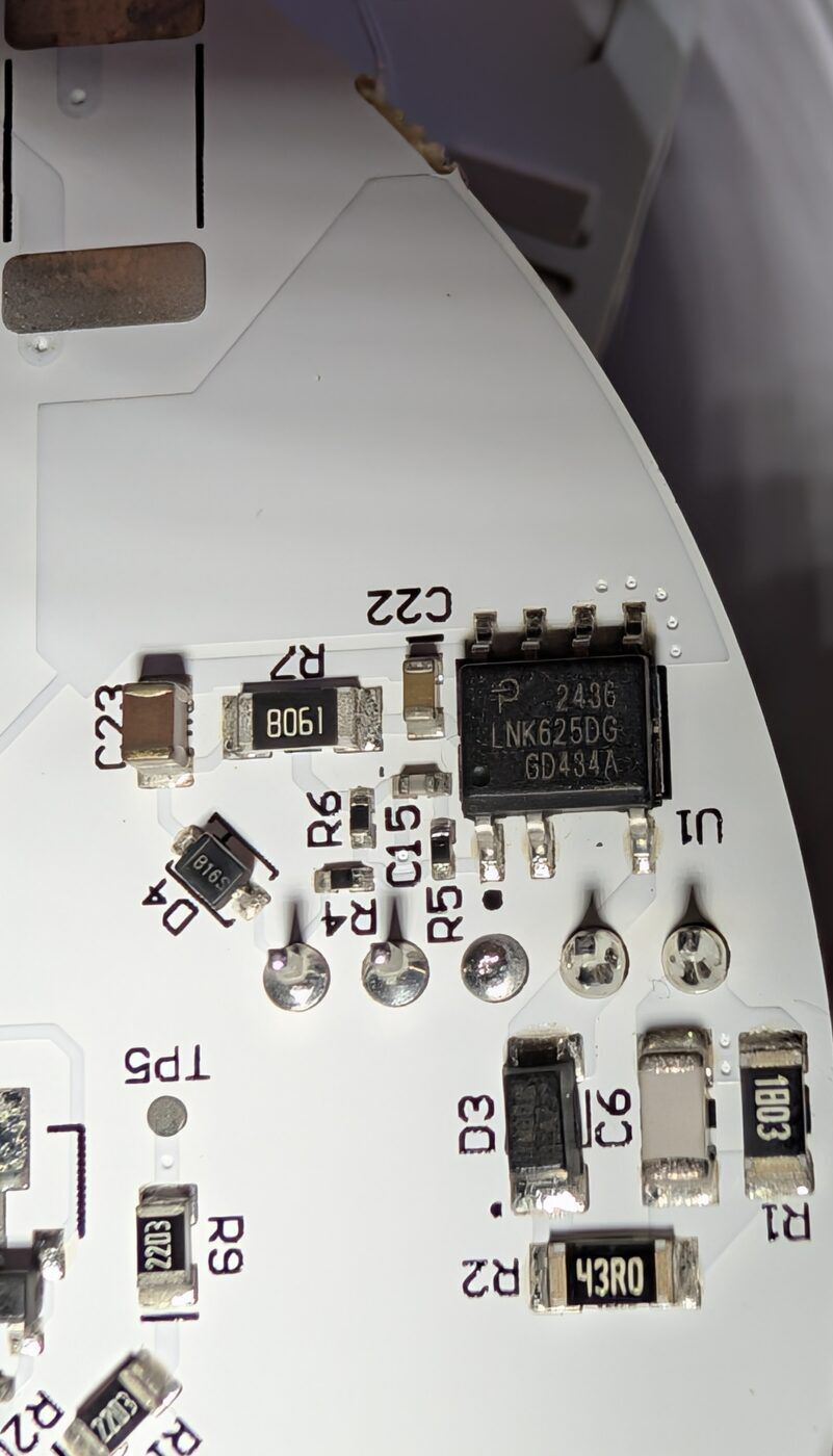
The wall model is powered from an AC line through a non-isolated switching regulator (an LNK625DG off-line switcher). Its ground is not your ground. Never connect a grounded USB-serial adapter to it while it’s plugged into the wall — do all flashing from a bench 3.3 V supply with the mains cord out, and only go back to mains for over-the-air updates after the first flash. Treat the board as live.
Build notes
The ESP-IDF/ESPHome toolchain for these is happiest built in a container. On macOS in particular, bind-mounting the build directory breaks the esp-idf install (symlink shenanigans); use a named volume for the .esphome build cache and copy the resulting firmware.factory.bin out. First flash over serial, everything after that over the air.
What you actually gain
Once it’s local, the diffuser is finally yours:
- No cloud, no account, no “service is down” — it works on a dead internet connection.
- Both bays readable and controllable independently (which the cloud app itself handles clumsily).
- Real automation: schedules, per-bay run-time auto-off timers enforced on-device (so they survive a hub reboot), do-not-disturb, and status you can drive however you like — I mapped device state onto the LEDs (a boot/connecting animation, a distinct “lost the hub” pattern, and a low-fragrance color).
- Cartridges that run until they’re actually empty, not until a counter says so.
The takeaway
None of this required breaking anything. The device handed me its firmware over an unauthenticated serial port, and the firmware handed me a production cloud identity in plaintext. The cartridge “authenticity” system leans entirely on a server that’s trivial to route around, while the one chip on the board that could have enforced it offline sits idle. This is a premium-priced product whose entire lock-in model is a polite request that you not look inside.
So look inside. It’s an ESP32. You already know what to do with those.